
Prerequisites
- FortiGate version 7.2.2 or higher is required.
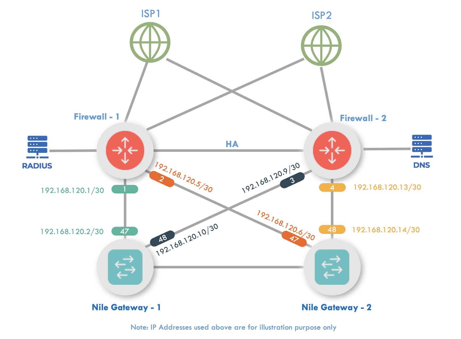
- Five unique /30 subnets:
- As we are designing a high-definition and an always-on service, we will be using Equal Cost Multi-Path (ECMP) to create 4 point-to-point links to act as a L3 transit between the NSB and the edge.
- The fifth /30 network will be used to host a Dynamic Host Configuration Protocol (DHCP) server. Alternatively, the customer can use their own managed DHCP server.
1. Interfaces
To setup Interfaces, navigate to Network → Interfaces → [WAN Interface]
Within the selected WAN port, fill in the following information:
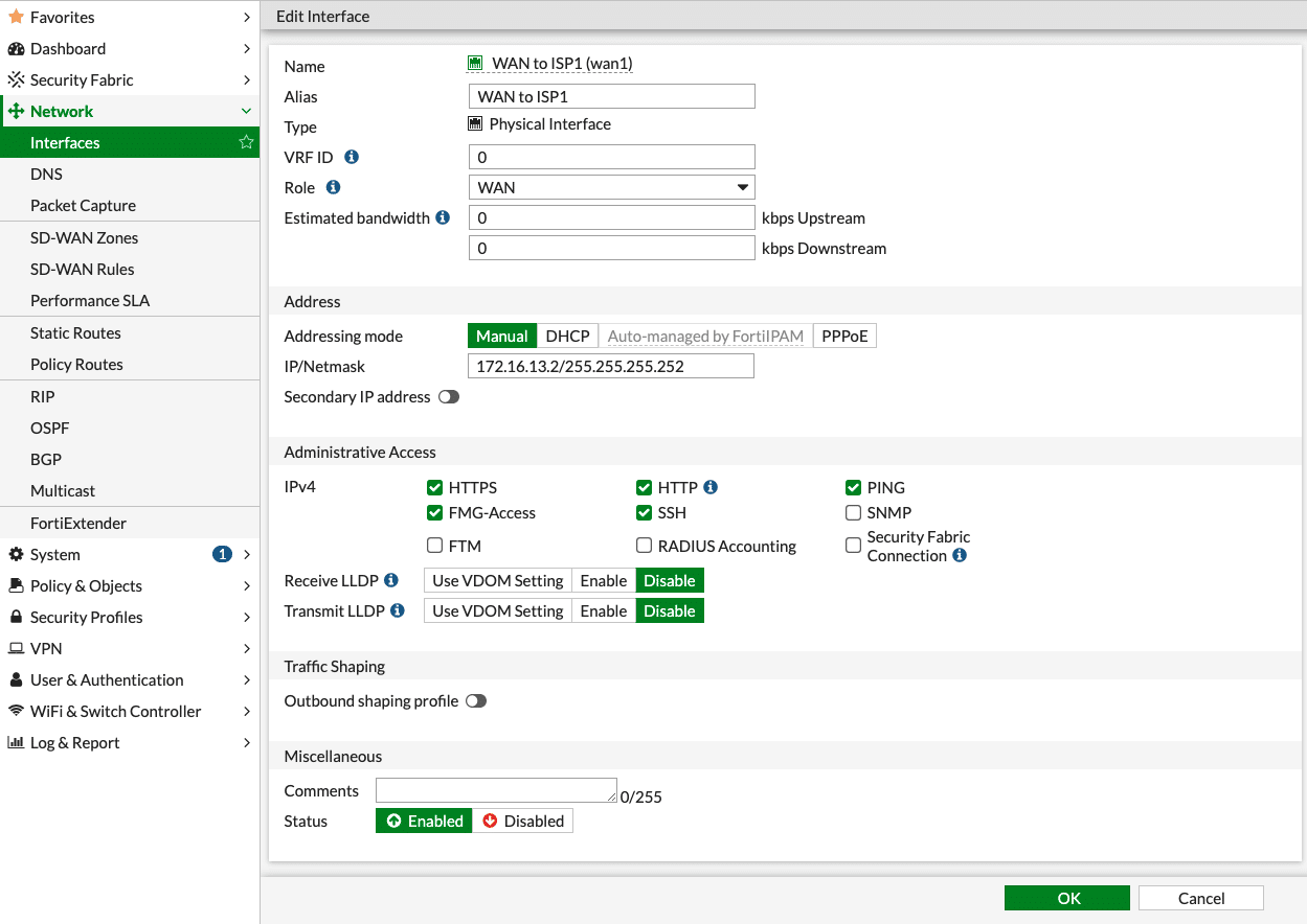
Name: ISP
Alias: Details of the ISP
VRF ID: Default (0)
Role: WAN
Addressing Mode: Manual
IP/Netmask: IP address/Netmask of WAN interface (our example used 172.16.13.2/30)
Administrative Access: Allow the required IPv4 services
Status: Enabled
Click the “Save” button when done.
Nile Gateway Interfaces
Expand on Network → Interfaces → Create New → Interface

Name: NSB Switch
Type: Software Switch
VRF ID: Default (0)
Interface Members: Select 2 available ports (in the image, 4 ports are selected, but 2 will be enough)
Role: LAN
Addressing Mode: Manual
IP/Netmask: IP address of interface (Our example used 192.168.120.18/30 (Used as DHCP server))
Secondary IP address: Enable (Radio button turned on)
Create New:
IP/Netmask: Example used (192.168.120.1/30)
IP/Netmask: Example used (192.168.120.5/30)
IP/Netmask: Example used (192.168.120.9/30)
IP/Netmask: Example used (192.168.120.13/30)
Administrative Access: Allow the required IPv4 services (PING should be enabled)
Receive LLDP: Enable
Transmit LLDP: Enable
Status: Enabled
Click the “Save” button when done.
2. Routing
Customers need to use Static Routing to add the default route towards the WAN interfaces, but on the LAN, it is recommended to use OSPF whenever possible, if there are certain limitations where OSPF cannot be used on the FortiGate, then create static routing on the LAN as well.
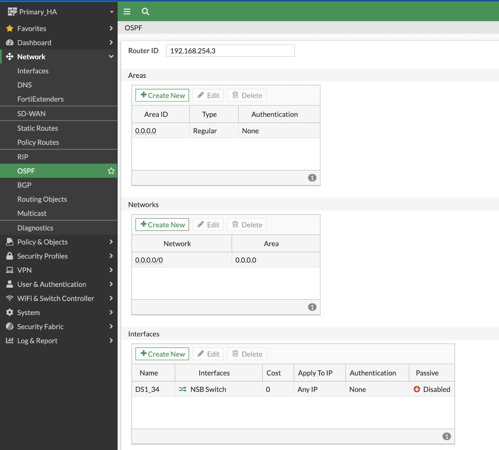
OSPF (LAN):
1. Expand on Network → OSPF:
Router ID: Fortinet’s best practice is to NOT use the existing IP of the interface, as Area ID is defined as 0.0.0.0, we are using the Router ID as 0.0.0.1 in this example.
Areas: Create New (Area ID: 0.0.0.0 || Type: Regular || Authentication: None)
Networks:Create New (Area: 0.0.0.0 || IP/Netmask: 0.0.0.0 0.0.0.0)
Interfaces: Create New (Name: NSB || Interface: NSB Switch || Cost: 0 || Authentication: None || Timers: Hello(1); Dead(4))
Inject Default Route: Always
Then click on “OK” to save the changes.
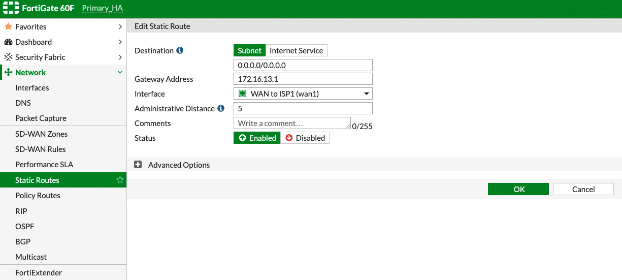
Static Routing (WAN):
1. Expand on Network → Static Routes → Create New:
Destination: Subnet (0.0.0.0/0)
Gateway Address: Enter the Gateway IP provided by the ISP
Interface: Select the WAN interface connected to the provider circuit
Administrative Distance: 5 (lower the AD, higher the priority)
Status: Enabled
Then click on “OK” to save the changes.
2. Repeat the same steps for setting up with a default static route for WAN2; set the AD as 10 while setting up the default route for WAN2, if WAN1 is desired as the primary link.
3. FortiGate Firewall Rules
FortiGate has an implicit rule of denying all the traffic.To ensure the NSB subnet and the Sensor subnet is able to access the Internet, a rule needs to be created.
The following example policy will allow any traffic coming from the NSB switch interfaces to the internet. The example rule is intended to be used as reference and should be modified to fit the customer needs. In case the customer wants to allow communication from Host A to Host B within the NSB, they will need to create firewall rules to allow that traffic to hairpin and enter into the NSB.
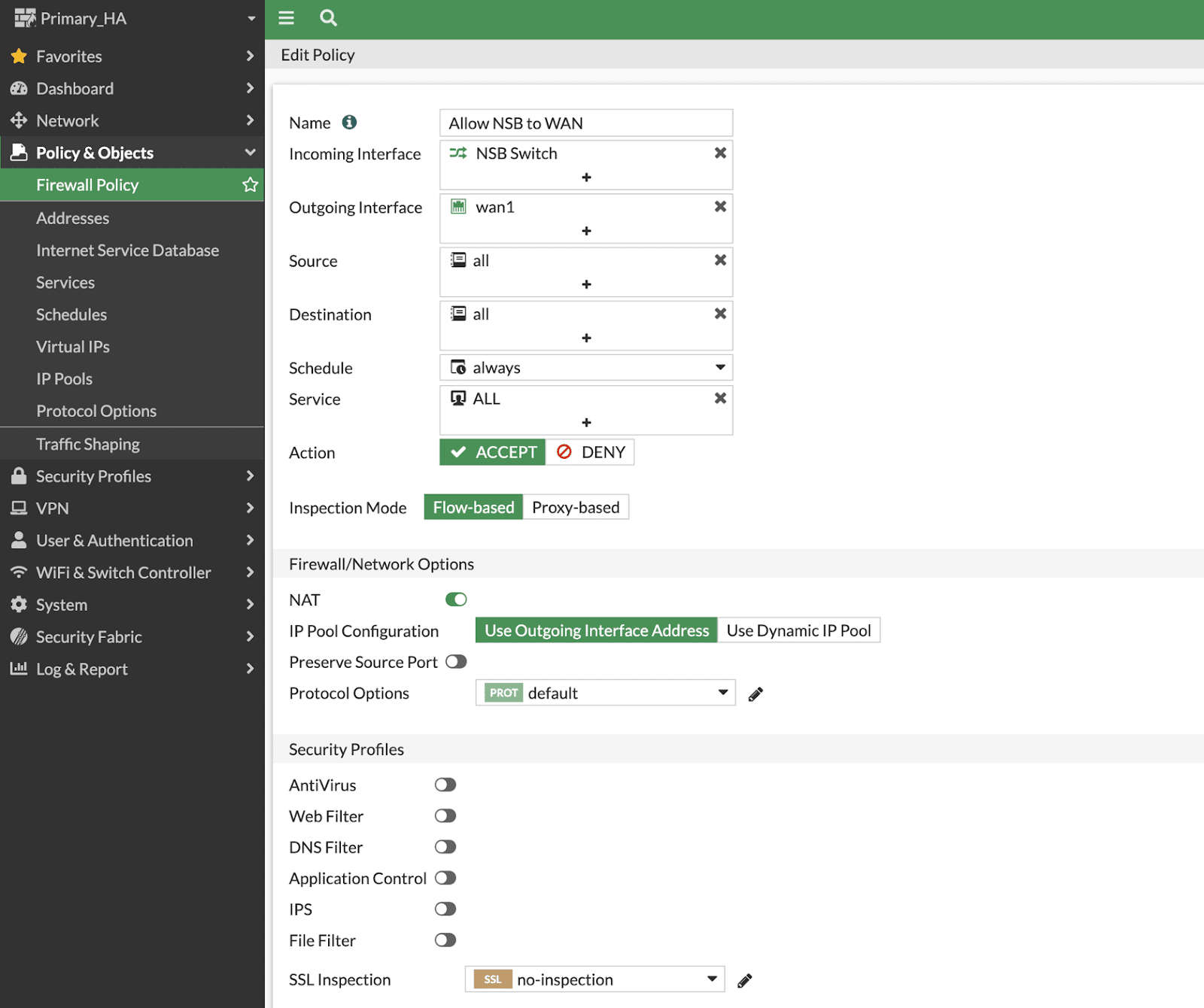
Outgoing to Internet
Navigate to Policy & Objects >> Firewall Policy >> Create New:
a. Name Provide a name to the rule
b. Incoming Interface Select the “NSB Switch”
c. Outgoing Interface WAN1
d. Source Create a source address with either a summarized subnet of all the subnets managed by the NSB or provide a IP range or select “Allow All”
e. Destination All
f. Schedule Always
g. Service Specify any specific service like HTTP/HTTPS to be allowed or allow all
h. Action Accept
i. Inspection Mode Flow based
j. Firewall/Network Options Enable NAT, Use Outgoing interface address for IP pool setup

NOTE
Note: NAT may need to be disabled while creating the firewall policy for some firewall rules to allow access to certain protocols (e.g., DHCP, DNS, Radius, NTP)