
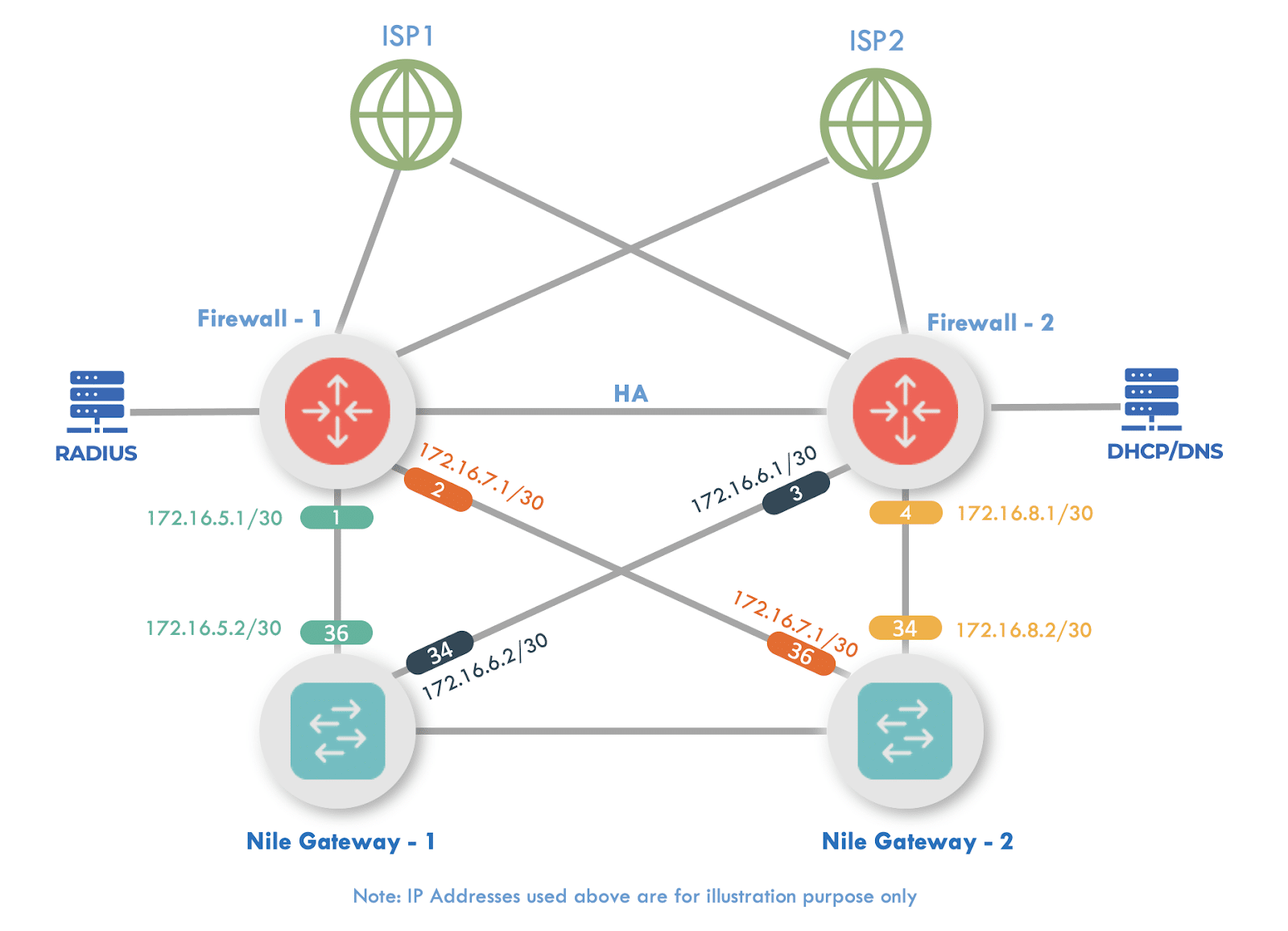
Topology Diagram

NOTE
Note: It is important to diagram the interface IP assignments. For illustration purposes, this document uses the following interfaces and IP subnets:
1. Zones
To define the Internet, LAN and NSB zones, go to Network g Zones:
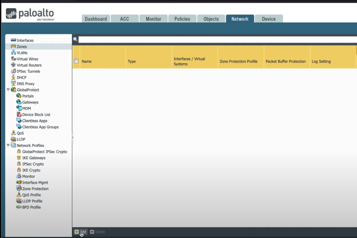
Figure 1
NSB
Click on +Add button (at the bottom of the Zone screen) to create a new zone:
-
- Name: NSB
- Log Setting: SNMP traps or syslog could be defined as needed.
(drop down menu)
-
- Type: Layer3 (drop down menu)
- Interfaces: Add the NSB assigned interfaces 1/1 to 1/4.
(+ Add button at bottom of Interfaces panel for each.)
- Zone Protection Profile: Define to match your environment.
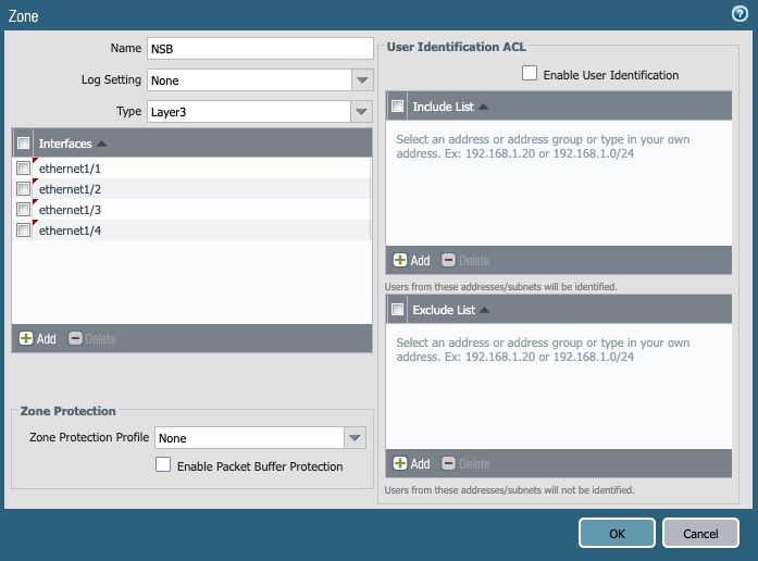
Figure 2
Internet
Click on +Add button (at the bottom of the Zone screen) to create another new zone:
- Name: Internet
- Log Setting: SNMP traps or syslog could be defined as needed.
- Type: Layer3
- Interfaces: Add the WAN interfaces 1/7 and 1/8.
- Zone Protection Profile: Define to match your environment.
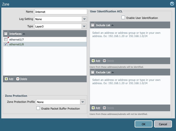
Figure 3
LAN
Repeat the Add Zones step to create the LAN zone and add the assigned interface 1/5 to it:
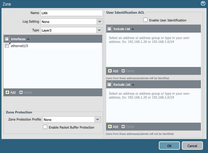
Figure 4
Once the above setup steps are complete, the Zones page looks like this:
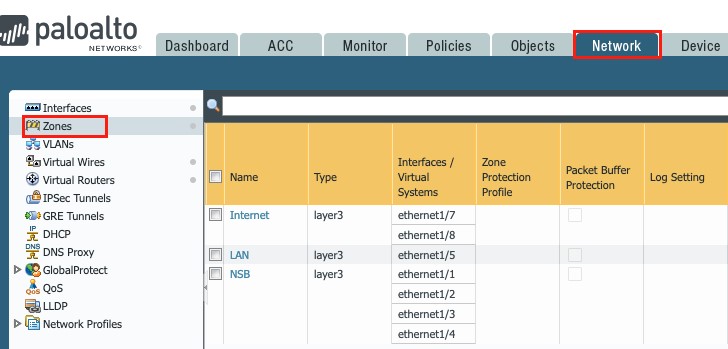
Figure 5
2. Profiles
Management Profile
Go to Network → Network Profiles → Interface Mgmt:
Click on + Add button, and enable the desired services with security concerns in mind.
The following screenshots illustrate two profiles: NSB and WAN:
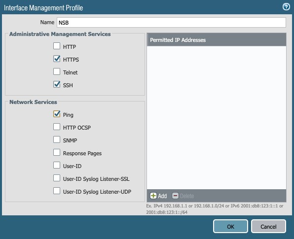
Figure 6
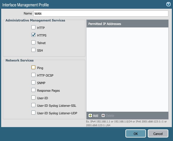
Figure 7
LLDP Profile
Go to Network → Network Profile → LLDP Profile
Click on the + Add button:
- Name: LLDP Enable
- Mode: transmit-receive
- Optional TLVS: Enable all 4 options (Port Description, System Name, System Description, System Capabilities)
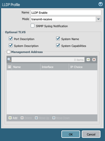
Figure 8
NSB Interfaces
Two interfaces (2) are needed for a single firewall, and four (4) for an Active-Passive set of two firewalls. This document is using Ethernet1/1 to Ethernet1/4 as the four uplinks to the NSB:
Ethernet1/1:
Click the Interface ethernet1/1, and set the following:
- Comment: Link to Nile GW-1
- Interface type: Layer3
- Config tab:
- Virtual Router: default
- Security Zone: NSB
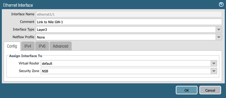
Figure 9
4. IPv4 tab:
a. Type: Static
b. IP: 16.7.1/30
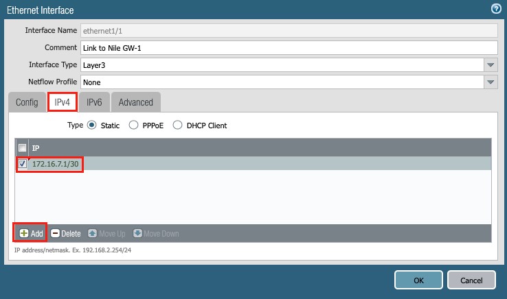
Figure 10
5. Advanced tab:
a. Management Profile: Select the NSB profile.
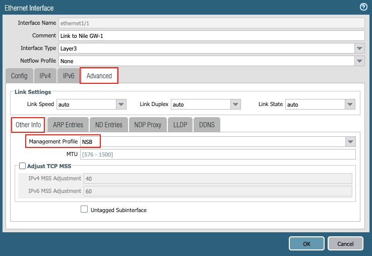
Figure 11
a. LLDP: Enable LLDP and Select the ‘LLDP enable’ profile
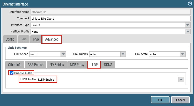
Figure 12
Repeat the same procedure for Ethernet1/2 through Ethernet1/4:
Ethernet1/2: 172.16.7.5/30
Ethernet1/3: 172.16.7.9/30
Ethernet1/4: 172.16.7.13/30
This completes the setup for the four uplink interfaces to the NSB.
WAN Interfaces
In this document, the firewall(s) is/are connected to two ISPs through interfaces Ethernet1/7 and Ethernet1/8, for redundancy purposes.
Ethernet1/7:
Click the Interface ethernet1/7, and set the following:
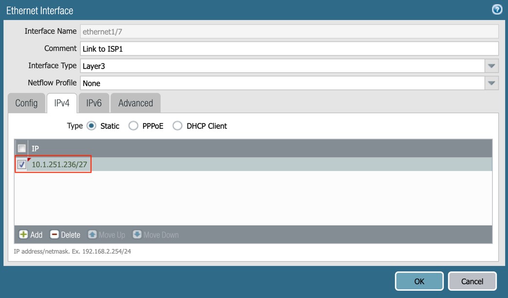
Figure 13
Ethernet1/8:
Click the Interface ethernet1/8, and set the following:
- Comment: Link to Nile ISP2
- Interface type: Layer3
- Config tab:
- Virtual Router: default
- Security Zone: Internet
- IPv4 tab:
- Type: Static
- IP: 1.252.236/27
- Advanced tab:
- Other Info:
- Management Profile: WAN
- Other Info:
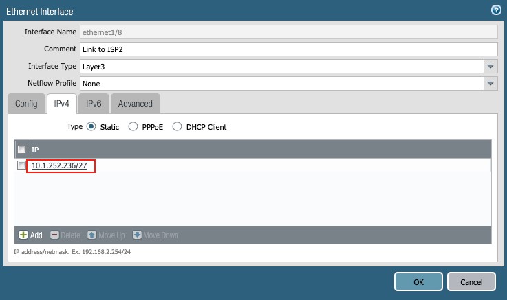
Figure 14
LAN subnet
This setting specifies the interface to a directly-attached server farm, or the core network. It is shown here for completion purposes:
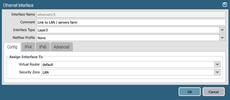
Figure 15
3. Routing
To set up routing on the PAN firewall, go to Network → Virtual Routers.
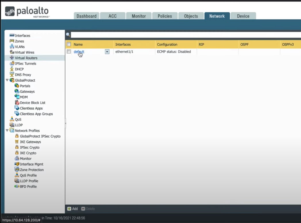
Figure 16
The virtual router default is used in this document, and all interfaces have already been added in the previous section. Click on “default” link to see the settings:
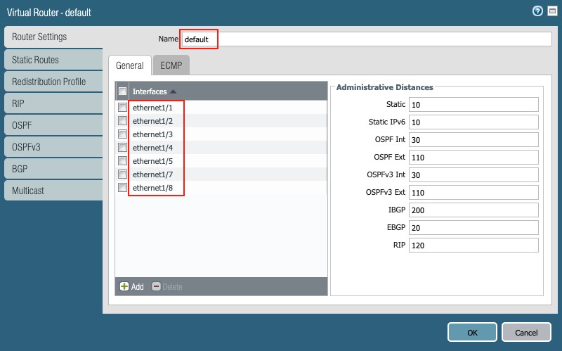
Figure 17
WAN Routing (static)
Static routing is used on the WAN with two (2) default routes added, for ISP1 and ISP2. ISP1 is the primary and receives a metric of 10. ISP2 acts as a backup with a metric of 100.
Click the ‘Static Routes’ selector in the Virtual Router panel.
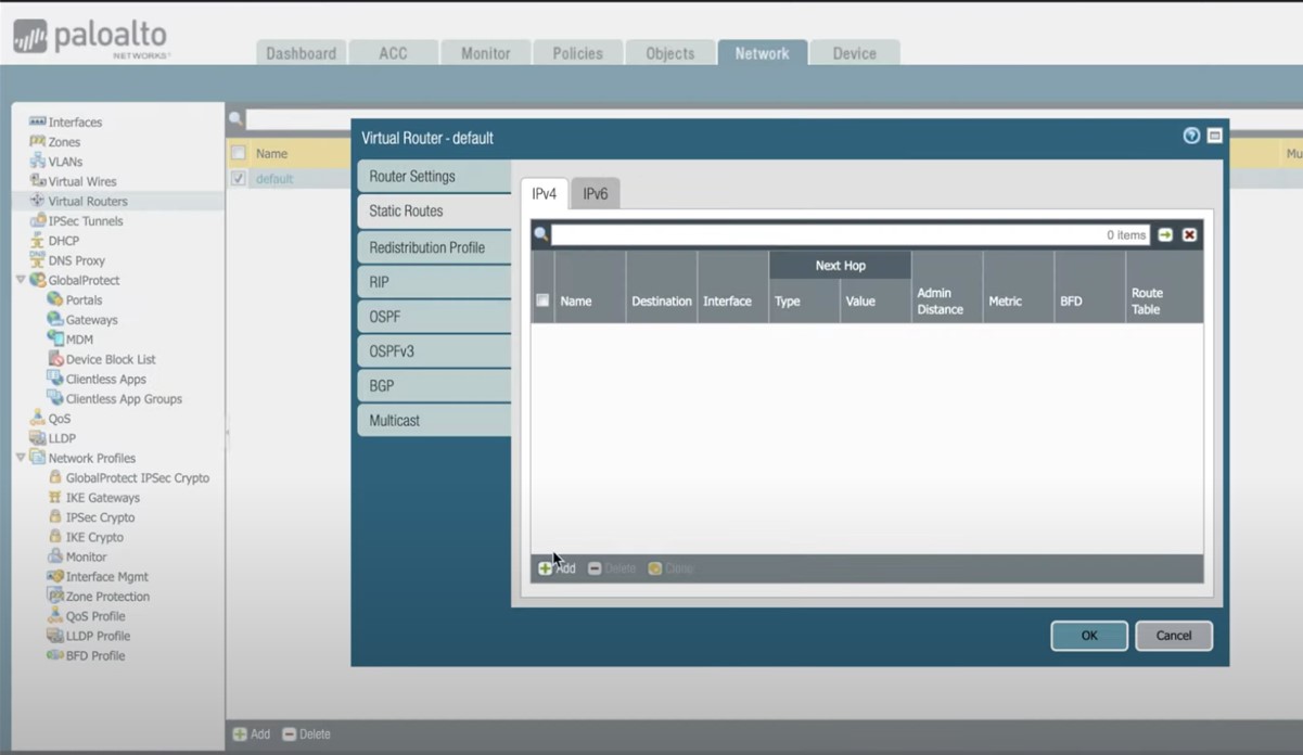
Figure 18
Click the ‘+ Add’ button in the pop-up to add 2 static routes as follows:
ISP1:
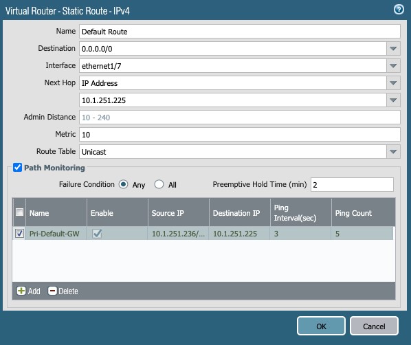
Figure 19
ISP2:
- Name: Backup Default Route
- Destination: 0.0.0/0
- Interface: ethernet1/8
- Next Hop: IP Address – 10.1.252.225
- Metric: 100
- Route Table: Unicast
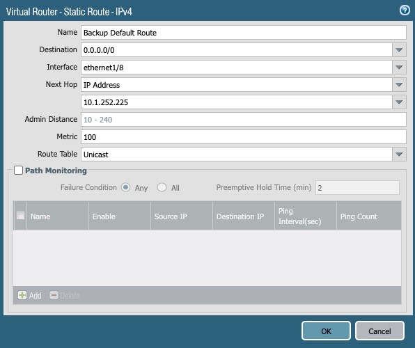
Figure 20
NSB Routing
Important:
For the Nile service to operate correctly, it is critical that the following subnets are routed back by the PAN firewall to the NSB gateways:
- NSB subnet
- Sensor subnet
- All client subnets
- Servers (DHCP, Radius, DNS) hosts/subnets
Two routing options to the Nile NSB are supported: static or dynamic (OSPF)
Option 1: Static routing with ECMP
In this document, the following subnets:
- NSB subnet: 16.8.0/24
- Sensor subnet: 16.9.0/24
- Client subnets: 16.10.0/24 – 172.16.15.0/24
Therefore, four (4) static routes are added to the aggregated subnet: 172.16.8.0/21, one for each of the downlinks to the Nile Gateways.
Since Nile traffic to the PAN firewall uses flow based ECMP routing through both Nile Gateways, it is important to enable ECMP on the firewall:
1.1 ECMP setup:
Go to Virtual-Router g default g Router Settings g ECMP
Select the following:
- Enable
- Max Path: 4
- Load Balance Method: Weighted Round Robin
- Add all interfaces to the NSB, namely ethernet1/1 to ethernet1/4
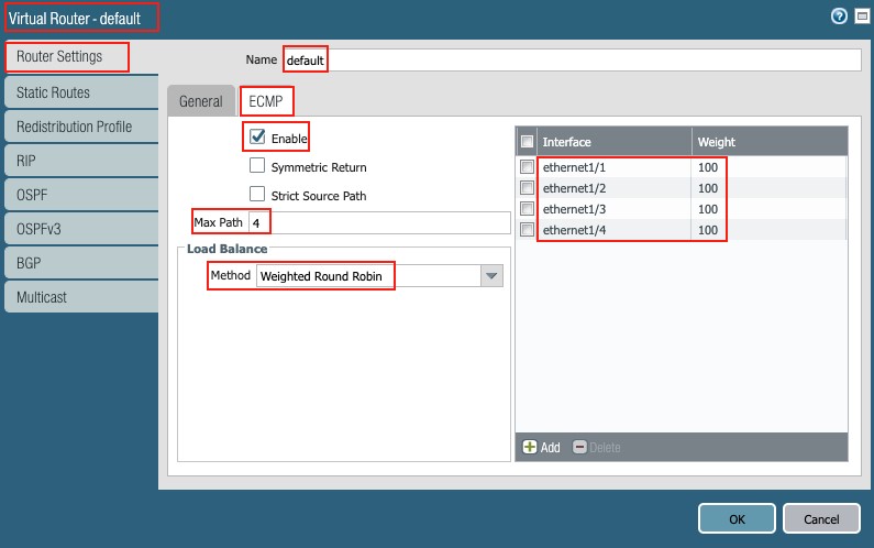
Figure 21
1.2 Static routes:
Add four (4) equal cost static routes for the aggregated subnet in this example:
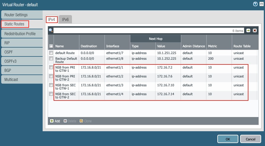
Figure 22
1.3 Route validation
Inspect the routing table and forwarding table to validate the static routes to the aggregate subnet 172.16.8.0/21, by clicking More Runtime Stats under Network g Virtual Routers:
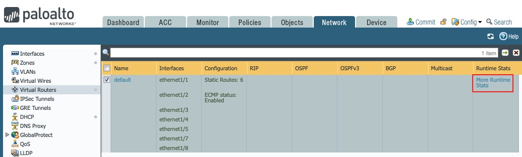
Figure 23
Routing table:
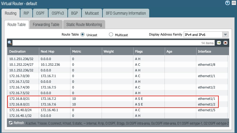
Figure 24
Forwarding table:
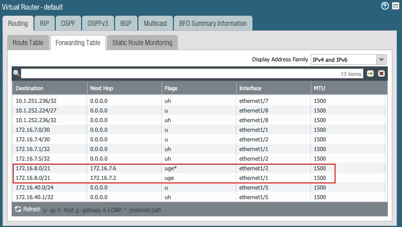
Figure 25
Option 2: Dynamic routing (OSPF)
2.1 ECMP setup:
The setup is the same as has been defined in the static routing section.
2.2 OSPF setup:
Go to Network g Virtual Routers g default g OSPF
Set the following:
- Enable: checked
- Reject Default Route: unchecked
- Router ID: 0.0.1 in this example (unique IP address)
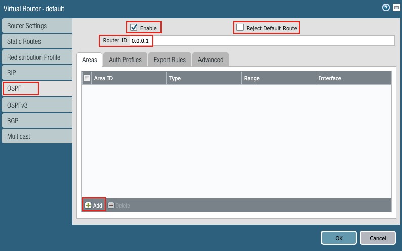
Figure 26
Add the interfaces connected to the NSB (ethernet1/1 to ethernet1/4), one by one:
- Areas: Click + Add
- Area ID: 0.0.0
- Type: Normal
- Interface: click + Add
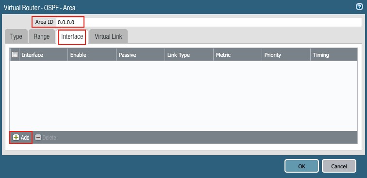
Figure 27
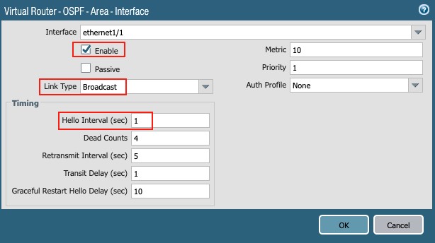
Figure 28
- Repeat the above for the other three (3) interfaces.
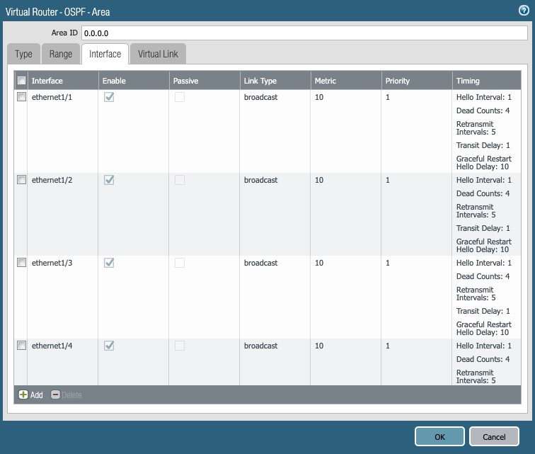
Figure 29
- Export Rules:
- Click the ‘Export Rules’ tab
- Allow Redistribute Default Route: checked
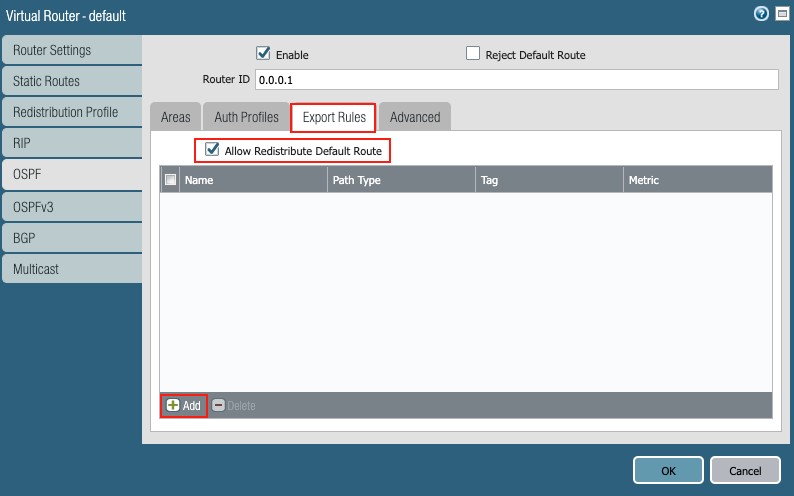
Figure 30
- Click + Add
- Name: 0.0.0/0
- New Path Type: Ext 1 (radio button)
- Metric: 10
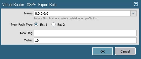
Figure 31
A summary of the virtual router ‘default’ setup is illustrated below:
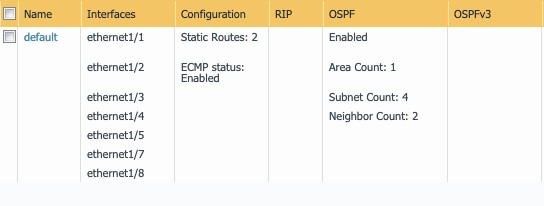
Figure 32
NOTE
If no aggregation is used, then four (4) equal-cost routes are needed for the NSB, sensors, and client subnets.
4. Firewall Rules
By default, Palo Alto Next Gen firewall allows intrazone (within the same zone) traffic and denies / blocks interzone (between two different zones) traffic.
As three zones were created in this document – (1) Internet, (2) NSB and (3) LAN – rules are needed to allow traffic from the LAN and NSB zones to the Internet zone, and between the NSB and LAN zones.
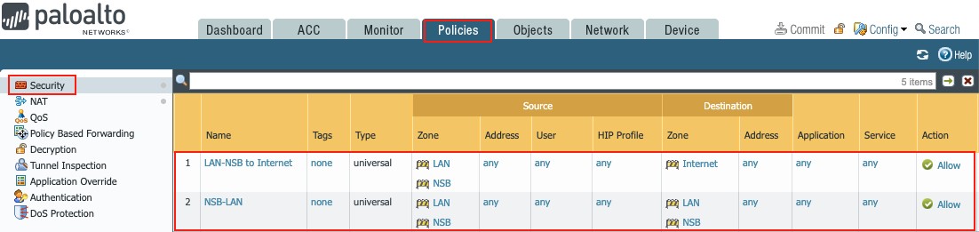
Figure 33
4.1 LAN/NSB Access to the Internet
Go to Policies g Security
Click on + Add to create the policy as follows:
- Name: LAN-NSB to Internet
- Rule Type: Universal
- Source column set:
- Source Zone: LAN and NSB
- Source Address: Any
- Source User: Any
- Source HIP Profile Any
- Destination column set:
- Destination Zone: Internet
- Destination Address: Any
- Application: Any
- Service/URL Category: Any
- Action: Allow
4.2 NSB/LAN Access
Go to Policy g Security
Click on + Add to create the policy as follows:
- Name: NSB-LAN
- Rule Type: Universal
- Source:
- Source Zone: LAN and NSB
- Source Address: Any
- Source User: Any
- Source HIP Profile Any
- Destination:
- Destination Zone: LAN and NSB
- Destination Address: Any
- Application: Any
- Service/URL Category: Any
- Action: Allow
NOTE
The above rules are provided as an example; it is up to customers to change them according to the requirements of their security policies.
5. NAT Rules
By default, the Palo Alto Next Gen Firewall does not NAT traffic. Source NAT rules are needed for internal traffic using private addresses to reach the Internet.
Since this document covers a dual ISP environment, two source NAT rules are needed for each ISP.
Go to Policies g NAT
Click on + Add to create the Source NAT rules:
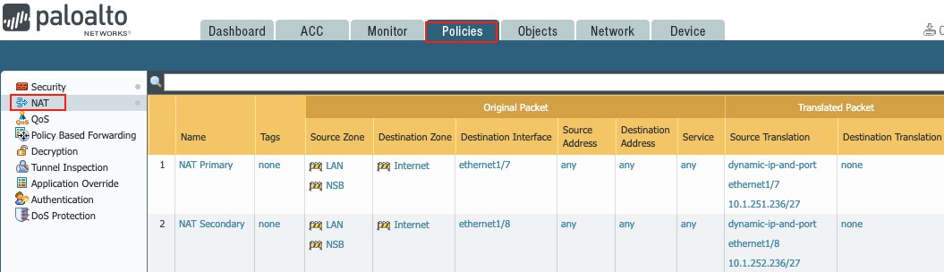
Figure 34
4.2 NSB/LAN Access
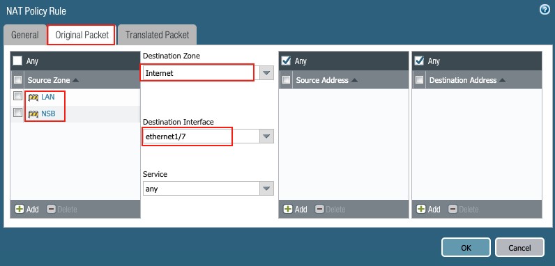
Figure 35
- Source Zone: NSB and LAN (check boxes)
- Destination Zone: Internet (from pull-down list)
- Destination Interface: ethernet1/7 (from pull-down list)
- Service: Any (from pull-down list)
- Source Address: Any (check box)
- Destination Address: Any (check box)
- Translated Packet tab:
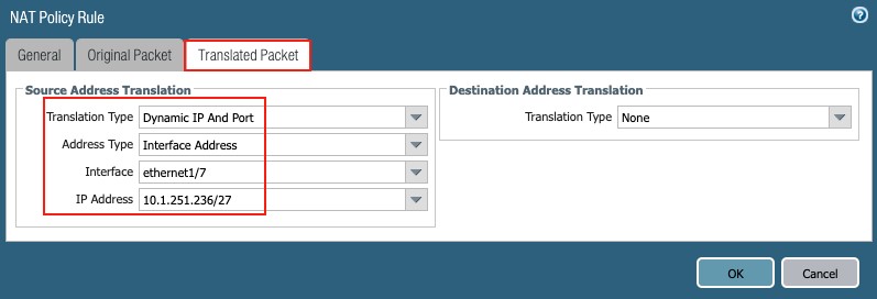
Figure 36
- Source Address Translation:
- Translation Type: Dynamic IP and Port (from drop-down list)
- Address Type: Interface Address (from drop-down list)
- Interface: ethernet1/7 (from drop-down list)
- IP Address: 1.251.236/27 (from drop-down list)
4.2 NSB/LAN Access
Repeat the previous step using interface ethernet1/8, with the Translated Packet tab reflecting the following:
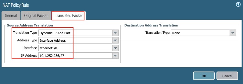
Figure 37
1. HA (Active-Passive)
It is important to abide by the Palo Alto prerequisites for Active/Passive HA (high availability), as detailed in the following URL:
HA Ports
The HA ports could be dedicated or assigned based on the firewall model
In this document the following HA ports are utilized:
Control Link (HA1): Management
Data Link (HA2): ethernet1/6
Active Firewall
General Setup
Go to Device → High Availability → General
where the setup is divided into sections accessible through their own setup button.
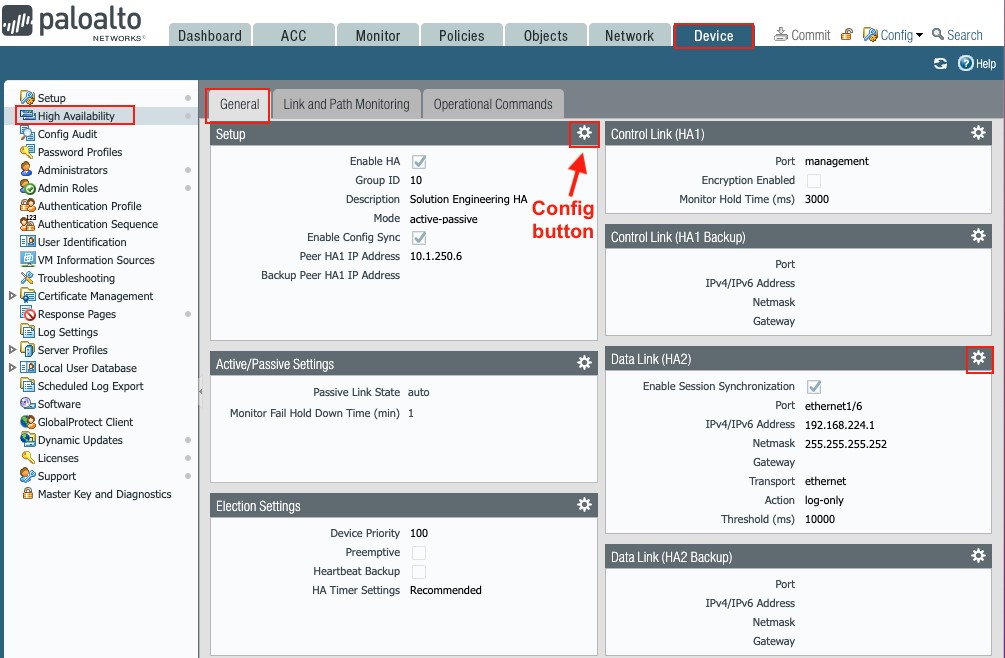
Figure 38
Click the config button within each section to access the settings, starting with the Setup section:
- Setup (config button)
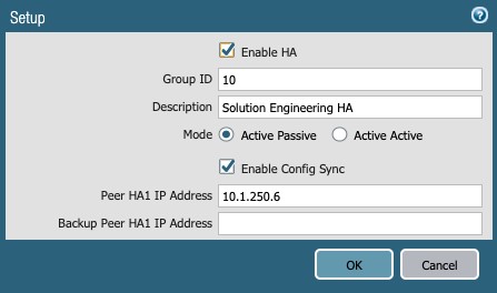
Figure 39
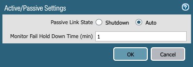
Figure 40
- Passive Link State: Auto
- Control Link (HA1) (config button)
- The management port is used in this document
- Data Link (HA2) (config button)
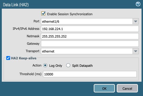
Figure 41
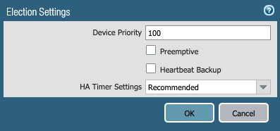
Figure 42
Link and Path Monitoring
This setup defines the failover conditions and could use link and/or path monitoring to determine what causes a PAN firewall to fail over.
This document covers link monitoring of the NSB and WAN interfaces.
Two groups are defined: NSB and WAN
The NSB link monitoring comprises the active interfaces on each firewall, namely:
- Ethernet1/1 and ethernet1/2 on the Active firewall
- Ethernet1/3 and ethernet1/4 on the Passive firewall
The WAN link monitoring has both ISP1 and ISP2 interfaces (Dual ISP).
To set up HA link monitoring,
go to Device → High Availability → Link and Path Monitoring,
Define as shown:
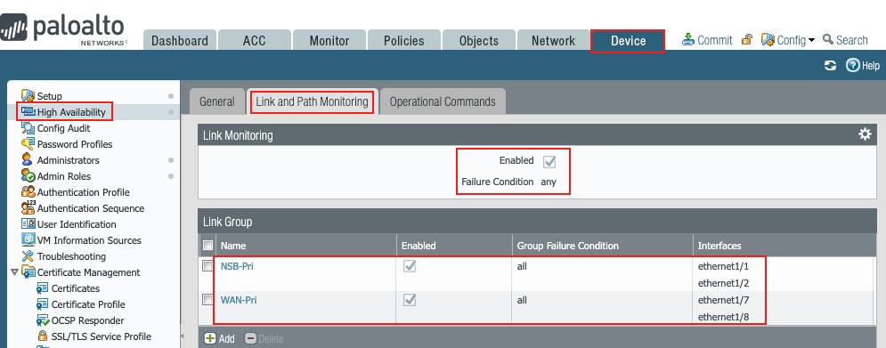
Figure 43
Passive Firewall
General Setup
Repeat the setup steps taken in the Active firewall section to define HA on the Passive firewall paying attention to the following:
- Same group ID: 10
- Peer HA1 IP Address Active firewall management port IP
- Higher Device priority in Election Settings
- Data Link (HA2) IP Address: 192.168.224.2
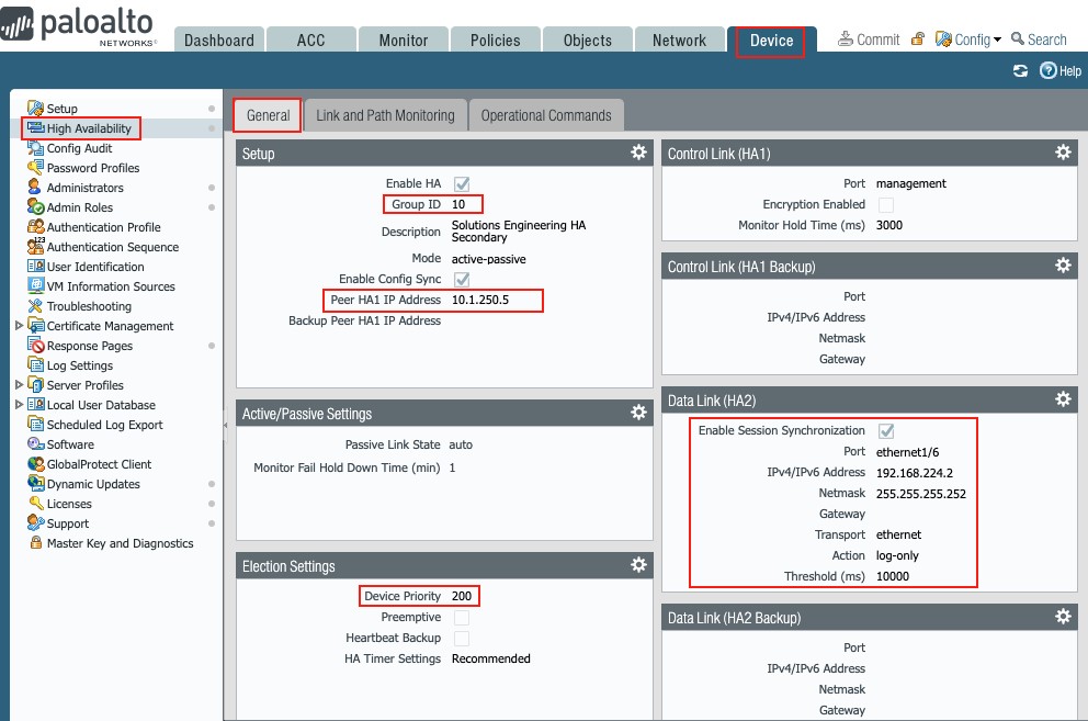
Figure 44
Link and Path Monitoring
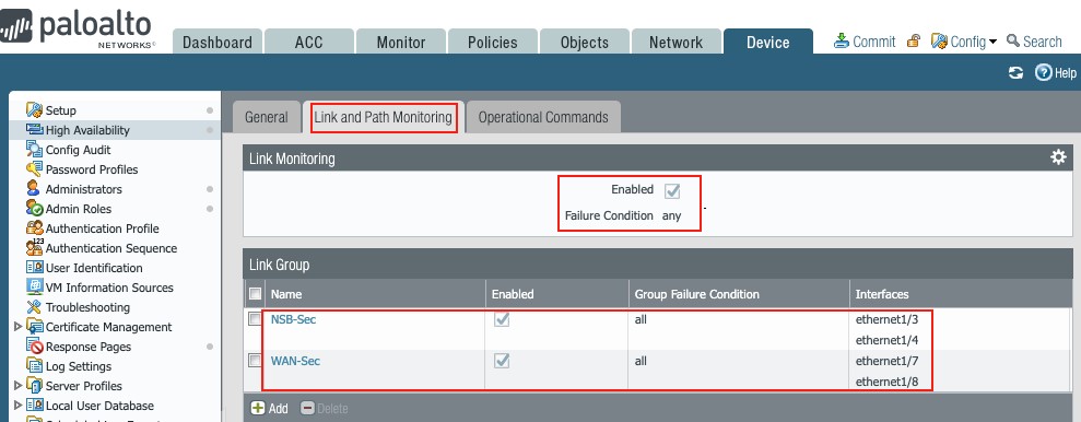
Figure 45
Click the Commit button on each firewall to save the setup and make it operational.
Once synchronized, the High Availability widget on each firewall should reflect their state and that their setup is in sync:
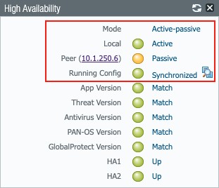
Figure 46
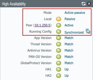
Figure 47
NOTE